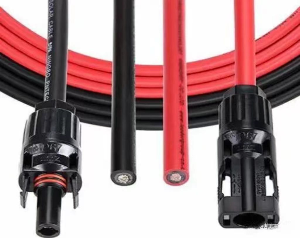
Photovoltaic cables are the basis of supporting electrical equipment in photovoltaic systems. The amount of cables used in photovoltaic systems exceeds that of general power generation systems, and they are also one of the important factors affecting the efficiency of the entire system.
Although photovoltaic DC and AC cables account for about 2-3% of the cost of distributed photovoltaic systems, actual experience has found that using the wrong cables may lead to excessive line loss in the project, low power supply stability, and other factors that reduce project returns.
Therefore, choosing the right cables can effectively reduce the accident rate of the project, improve power supply reliability, and facilitate construction, operation and maintenance.
Types of photovoltaic cables
According to the system of photovoltaic power stations, cables can be divided into DC cables and AC cables. According to different uses and usage environments, they are classified as follows:
DC cables are mostly used for:
Series connection between components;
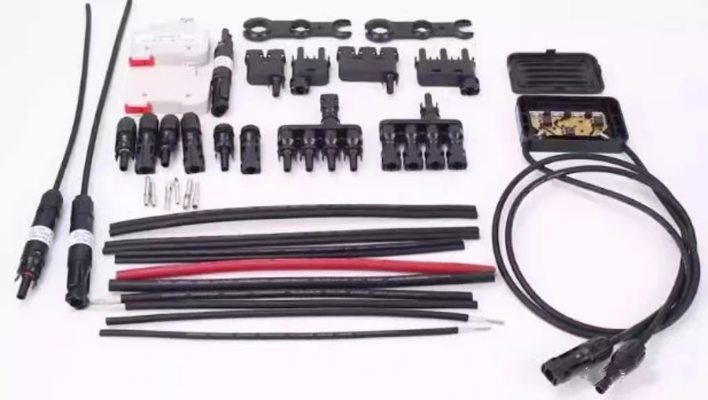
Parallel connection between strings and between strings and DC distribution boxes (combiner boxes);
Between DC distribution boxes and inverters.
AC cables are mostly used for:
Connection between inverters and step-up transformers;
Connection between step-up transformers and distribution devices;
Connection between distribution devices and power grids or users.
Requirements for photovoltaic cables
The cables used in the low-voltage DC transmission part of the solar photovoltaic power generation system have different requirements for the connection of different components due to different use environments and technical requirements. The overall factors to be considered are: cable insulation performance, heat and flame retardant performance, anti-aging performance and wire diameter specifications. DC cables are mostly laid outdoors and need to be moisture-proof, sun-proof, cold-proof, and UV-proof. Therefore, DC cables in distributed photovoltaic systems generally choose photovoltaic-certified special cables. This type of connecting cable uses a double-layer insulation sheath, which has excellent resistance to UV, water, ozone, acid, and salt erosion, excellent all-weather capability and wear resistance. Considering the DC connector and the output current of the photovoltaic module, the commonly used photovoltaic DC cables are PV1-F1*4mm2, PV1-F1*6mm2, etc.
AC cables are mainly used from the AC side of the inverter to the AC combiner box or AC grid-connected cabinet. For the AC cables installed outdoors, moisture, sun, cold, UV protection, and long-distance laying should be considered. Generally, YJV type cables are used; for AC cables installed indoors, fire protection and rat and ant protection should be considered.
Cable material selection
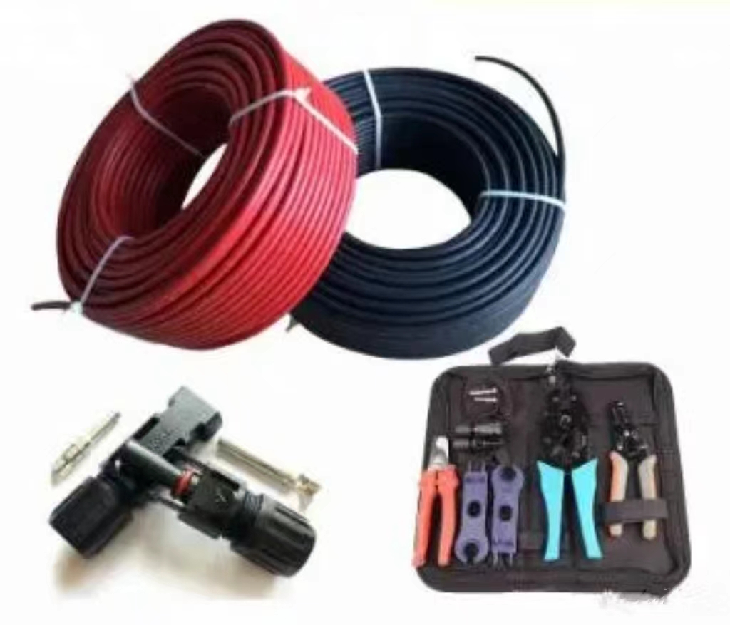
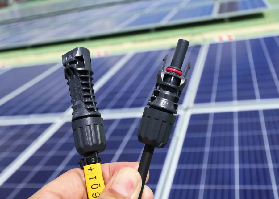
The DC cables used in photovoltaic power stations are mostly used for long-term outdoor work. Due to the limitations of construction conditions, connectors are mostly used for cable connection. Cable conductor materials can be divided into copper core and aluminum core.
Copper core cables have better antioxidant capacity than aluminum, longer life, better stability, lower voltage drop and lower power loss. In construction, copper cores are more flexible and allowable bending radius is small, so it is easy to turn and pass through pipes. Moreover, copper cores are fatigue-resistant and not easy to break after repeated bending, so wiring is convenient. At the same time, copper cores have high mechanical strength and can withstand large mechanical tension, which brings great convenience to construction and laying, and also creates conditions for mechanized construction.
On the contrary, due to the chemical properties of aluminum, aluminum core cables are prone to oxidation (electrochemical reaction) during installation, especially creep, which can easily lead to failures.
Therefore, although the cost of aluminum core cables is low, for the sake of project safety and long-term stable operation, Rabbit Jun recommends using copper core cables in photovoltaic projects.
Calculation of photovoltaic cable selection
Rated current
The cross-sectional area of DC cables in various parts of the photovoltaic system is determined according to the following principles: The connecting cables between solar cell modules, the connecting cables between batteries, and the connecting cables of AC loads are generally selected with a rated current of 1.25 times the maximum continuous working current of each cable;
the connecting cables between solar cell arrays and arrays, and the connecting cables between batteries (groups) and inverters are generally selected with a rated current of 1.5 times the maximum continuous working current of each cable.
At present, the selection of cable cross-section is mainly based on the relationship between cable diameter and current, and the influence of ambient temperature, voltage loss, and laying method on the current carrying capacity of cables is often ignored.
In different use environments, the current carrying capacity of the cable, and it is recommended that the wire diameter should be selected upward when the current is close to the peak value.
The incorrect use of small-diameter photovoltaic cables caused a fire after the current was overloaded
Voltage loss
The voltage loss in the photovoltaic system can be characterized as: voltage loss = current * cable length * voltage factor. It can be seen from the formula that the voltage loss is proportional to the length of the cable.
Therefore, during on-site exploration, the principle of keeping the array to the inverter and the inverter to the grid connection point as close as possible should be followed.
In general applications, the DC line loss between the photovoltaic array and the inverter does not exceed 5% of the array output voltage, and the AC line loss between the inverter and the grid connection point does not exceed 2% of the inverter output voltage.
In the process of engineering application, the empirical formula can be used: △U=(I*L*2)/(r*S)
△U: cable voltage drop-V
I: cable needs to withstand the maximum cable-A
L: cable laying length-m
S: cable cross-sectional area-mm2;
r: conductor conductivity-m/(Ω*mm2;), r copper=57, r aluminum=34
When laying multiple multi-core cables in bundles, design needs to pay attention to points
In actual application, considering factors such as cable wiring method and routing restrictions, the cables of photovoltaic systems, especially AC cables, may have multiple multi-core cables laid in bundles.
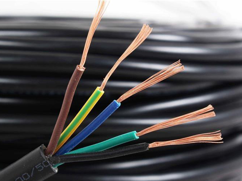
For example, in a small-capacity three-phase system, the AC outgoing line uses “one line four cores” or “one line five cores” cables; in a large-capacity three-phase system, the AC outgoing line uses multiple cables in parallel instead of single-core large-diameter cables.
When multiple multi-core cables are laid in bundles, the actual current carrying capacity of the cables will be attenuated by a certain proportion, and this attenuation situation needs to be considered at the beginning of the project design.
Cable laying methods
The construction cost of cable engineering in photovoltaic power generation projects is generally high, and the choice of laying method directly affects the construction cost.
Therefore, reasonable planning and correct selection of cable laying methods are important links in cable design work.
The cable laying method is comprehensively considered based on the project situation, environmental conditions, cable specifications, models, quantity and other factors, and is selected according to the requirements of reliable operation and easy maintenance and the principle of technical and economic rationality.
The laying of DC cables in photovoltaic power generation projects mainly includes direct burial with sand and bricks, laying through pipes, laying in troughs, laying in cable trenches, laying in tunnels, etc.
The laying of AC cables is not much different from the laying methods of general power systems.
DC cables are mostly used between photovoltaic modules, between strings and DC combiner boxes, and between combiner boxes and inverters.
They have small cross-sectional areas and large quantities. Usually, the cables are tied along the module brackets or laid through pipes. When laying, the following should be considered:
For connecting cables between modules and connecting cables between strings and combiner boxes, the module brackets should be used as the channel support and fixation for cable laying as much as possible, which can reduce the impact of environmental factors to a certain extent.
The force of cable laying should be uniform and appropriate, and should not be too tight. The temperature difference between day and night in photovoltaic sites is generally large, and thermal expansion and contraction should be avoided to prevent cable breakage.
The photovoltaic material cable leads on the surface of the building should take into account the overall aesthetics of the building.
The laying position should avoid laying cables on the sharp edges of walls and brackets to avoid cutting and grinding the insulation layer to cause short circuits, or shearing force to cut the wires and cause open circuits.
At the same time, problems such as direct lightning strikes on the cable lines should be considered.
Reasonably plan the cable laying path, reduce crossings, and combine laying as much as possible to reduce earth excavation and cable usage during project construction.
Photovoltaic cable cost information
The price of qualified photovoltaic DC cables on the market currently varies according to the cross-sectional area and purchase volume.
In addition, the cost of the cable is related to the design of the power station. Optimized component layout can save the use of DC cables.
Generally speaking, the cost of photovoltaic cables ranges from about 0.12 to 0.25/W. If it exceeds too much, it may be necessary to check whether the design is reasonable or whether special cables are used for special reasons.
Summary
Although photovoltaic cables are only a small part of the photovoltaic system, it is not as easy as imagined to choose suitable cables to ensure low accident rate of the project, improve power supply reliability, and facilitate construction, operation and maintenance. I hope that the introduction in this article can provide you with some theoretical support in future design and selection.
Please feel free to contact us for further information on solar cables.
sales5@lifetimecables.com
Tel/Wechat/Whatsapp:+86 19195666830
Post time: Jun-19-2024

