In recent years, the technology of the photovoltaic industry has developed faster and faster, the power of single components has become larger and larger, the current of strings has also become larger and larger, and the current of high-power components has reached more than 17A.
In terms of system design, the use of high-power components and reasonable over-matching can reduce the initial investment cost and cost per kilowatt-hour of the system.
The cost of AC and DC cables in the system accounts for a large proportion. How should the design and selection be reduced to reduce costs?

Selection of DC cables
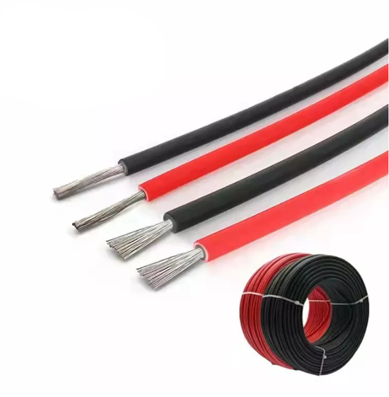
DC cables are installed outdoors. It is generally recommended to select irradiated and cross-linked photovoltaic special cables.
After high-energy electron beam irradiation, the molecular structure of the insulation layer material of the cable changes from linear to three-dimensional mesh molecular structure, and the temperature resistance level increases from non-cross-linked 70℃ to 90℃, 105℃, 125℃, 135℃, and even 150℃, which is 15-50% higher than the current carrying capacity of cables of the same specifications.
It can withstand drastic temperature changes and chemical erosion and can be used outdoors for more than 25 years.
When selecting DC cables, you need to choose products with relevant certifications from regular manufacturers to ensure long-term outdoor use.
The most commonly used photovoltaic DC cable is the PV1-F 1*4 4 square cable. However, with the increase of photovoltaic module current and the increase of single inverter power, the length of DC cable is also increasing, and the application of 6 square DC cable is also increasing.
According to relevant specifications, it is generally recommended that the loss of photovoltaic DC should not exceed 2%. We use this standard to design how to choose DC cable.
The line resistance of PV1-F 1*4mm2 DC cable is 4.6mΩ/meter, and the line resistance of PV 6mm2 DC cable is 3.1mΩ/meter. Assuming that the working voltage of the DC module is 600V, the voltage drop loss of 2% is 12V.
Assuming that the module current is 13A, using 4mm2 DC cable, the distance from the farthest end of the module to the inverter is recommended not to exceed 120 meters (single string, excluding positive and negative poles).
If it is greater than this distance, it is recommended to choose 6mm2 DC cable, but it is recommended that the distance from the farthest end of the module to the inverter is not more than 170 meters.
Selection of AC cables
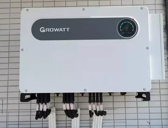
In order to reduce system costs, the components and inverters of photovoltaic power stations are rarely configured in a 1:1 ratio. Instead, a certain amount of over-matching is designed according to lighting conditions, project needs, etc.
For example, for a 110KW component, a 100KW inverter is selected. According to the 1.1 times over-matching calculation on the AC side of the inverter, the maximum AC output current is about 158A.
The selection of AC cables can be determined according to the maximum output current of the inverter. Because no matter how much the components are over-matched, the current of the inverter AC input will never exceed the maximum output current of the inverter.
Commonly used photovoltaic system AC copper cables include BVR and YJV and other models. BVR means copper core polyvinyl chloride insulated soft wire, YJV cross-linked polyethylene insulated power cable.
When selecting, pay attention to the voltage level and temperature level of the cable. Choose flame-retardant type. Cable specifications are expressed by core number, nominal cross-section and voltage level: single-core branch cable specification expression, 1*nominal cross-section, such as: 1*25mm 0.6/1kV, indicating a 25 square cable.
Specifications of multi-core twisted branch cables: the number of cables in the same loop * nominal cross-section, such as: 3*50+2*25mm 0.6/1KV, indicating 3 50 square live wires, a 25 square neutral wire and a 25 square ground wire.
What is the difference between single-core cable and multi-core cable?
Single-core cable refers to a cable with only one conductor in an insulation layer. Multi-core cable refers to a cable with more than one insulated core. In terms of insulation performance, both single-core and multi-core cables must meet national standards.
The difference between multi-core cable and single-core cable is that single-core cable is directly grounded at both ends, and the metal shielding layer of the cable may also generate circulating current, resulting in loss;
Multi-core cable is generally a three-core cable, because during cable operation, the sum of the currents flowing through the three cores is zero, and there is basically no induced voltage at both ends of the cable metal shielding layer.
From the perspective of circuit capacity, for single-core and multi-core cables, the rated current carrying capacity of single-core cables is greater than that of three-core cables for the same cross-section;
The heat dissipation performance of single-core cables is greater than that of multi-core cables. Under the same load or short circuit conditions, the heat generated by single-core cables is less than that of multi-core cables, which is safer;
From the perspective of cable laying, multi-core cables are easier to lay, and cables with inner and multi-layer double-layer protection are safer; single-core cables are easier to bend during laying, but the difficulty of laying over long distances is greater for single-core cables than for multi-core cables.
From the perspective of cable head installation, single-core cable heads are easier to install and convenient for line division. In terms of price, the unit price of multi-core cables is slightly higher than that of single-core cables.
Photovoltaic system wiring skills
The lines of the photovoltaic system are divided into DC and AC parts. These two parts need to be wired separately. The DC part is connected to the components, and the AC part is connected to the power grid.
There are many DC cables in medium and large power stations. In order to facilitate future maintenance, the line numbers of each cable should be firmly attached. Strong and weak power lines are separated. If there are signal lines, such as 485 communications, they should be routed separately to avoid interference.
When routing the wires, prepare conduits and bridges. Try not to expose the wires. It will look better if the wires are routed horizontally and vertically. Try not to have cable joints in conduits and bridges because they are inconvenient to maintain. If aluminum wires replace copper wires, reliable copper-aluminum adapters must be used.
In the entire photovoltaic system, cables are a very important component, and their cost share in the system is increasing. When we design a power station, we need to save system costs as much as possible while ensuring the reliable operation of the power station.
Therefore, the design and selection of AC and DC cables for photovoltaic systems are particularly important.
Please feel free to contact us for further information on solar cables.
sales5@lifetimecables.com
Tel/Wechat/Whatsapp:+86 19195666830
Post time: 2024-06-17


